I have used Pachmayr recoil pads since the late 70's in conjunction with
others such as those made by Silver's, Griffin and Howe and an imported
pad that NECG has sold for years. But the mainstay for decades was always the
Pachmayr. The rubber material used before the advent of the Decelerator
ground and finished up well and held up great under heavy field
conditions. Every now and then I receive an older Classic rifle that arrives
for a 30 year clean and oil or to replace a barrel and I have never felt a
need to replace any 752 Old English pads from that era.
This rifle was built in 1983 and pitched up a year ago for its 3rd barrel. It
has never been a safe queen.
This 416 Rigby has been used in Africa as a client loaner, a backup and
culling rifle from the early 90's and it appears this old 752 has never ever
been wiped down or cleaned up with lighter fluid. But it's still very much in
service.
I can't remember the year the Pachmayr went to the
Decelerator material. Those newly engineered pads seemed to work OK,
gave a little more in the initial recoil moment but still was the best
game in town for my rifles. Granted you had to modify the way you
finished them up but what else is new. Like the old rubber 752 the
decelerator ground and finished up well and offered sufficient density for
Leather covered pad application when required.
The last couple of years however Pachmayr has out done themselves in their
lack of quality control. There is nothing worse than grinding a pad to fit
and running into what I will call a bark pocket, or some hidden material
that managed to fall into the casting procedure while under
construction.
None of these cavities showed on the exterior of the pad as it came out of
the Blister Pack, just fantastic isn't it. These pads were removed shortly
after installation.
Call Lyman to complain and they will snd you a new pad, but who pays for the
lost and additional man hours required to fix this problem ? It not going to
be Lyman
I’m on the sticks and ready to shoot an old dugga boy when he finally stands up. Assuming, of course, a good shot presents itself. Two good bulls are bedded down in the thick Zambezi Valley jesse about 30 yards in front of me. I can see one, but the brush hides the other from my view. Rob, my PH suggests I get on the other bull, but it’s too risky to move so I stay with the bull I’m on. We’ve been on their tracks for over 4 hours since early morning but lost them about 30 minutes ago. Rob was about to call the whole thing off when we heard the faint whistle from the lead tracker – the track has been found and we’re close. A few yards further into the bush, the bull is spotted, Rob gets the sticks up and I’m in position. Now we wait...
So far, I’ve taken three good cape buffalo bulls with the Echols Classic M98 450 Rigby; one in Tanzania in 2022 and two more here in Mozambique 2024. Each has been stung hard by the 450 gr. TSX at 2350 fps prompting the PH’s to say things like, “That 450 nocks the socks off him.” and “That 450 really barks, hey.” It does hit with authority I will say so myself – no doubt about it. Obviously, the 450 Rigby case supports more powerful performance, but for controllability, shootability and with cape buffalo as the primary quarry, these loads are fine. To put things in perspective, my handloads for buffalo are about the same power level as a 450 Lott.
The bark of the mighty 450 Rigby has been so effective, that up until now, I haven’t had the need or the opportunity to see how well the whole package performs when things get interesting, which is, as we all know by now, what this gun is built for. This is about to change...
But before I get to that, some more of the back story first. In addition to the normal range work, I have done a fair amount of practice with the rifle to get familiar with its personality. In March of 2024 I visited Tim Fallon’s FTW Ranch in Barksdale TX for a few days to participate in their excellent SAAM Safari Course. The rifle performed great, shooting and handling exactly as I had hoped. The stock fit proved to be just about perfect. Mounting the gun to my shoulder, no head position adjustments are necessary to center the white front bead in the ghost ring. At 65 years old I wear progressive lens glasses while shooting the ghost ring set up, so I only need to focus on the front bead and the target. No mid sight v-notch to worry about. Speaking of the front bead, I set the gun up to shoot to the center of the bead at 75 yards. Some folks like a 6 o’clock hold. Not me. I want to put the bead right where I want the bullet to land. The gun swings great on movers. I’m not even aware of the ghost ring and I love the open-space awareness (that is, the opposite of looking through a scope) when engaging the target.
Recoil with my handloads, though stout is manageable. The gun is controllable too. For shooting big bores off African style shooting sticks, I like to wear a glove on my support hand and then place my support hand in the crotch of the shooting sticks with a firm grip on the fore end. I imagine this approach isn’t for everyone, but it works great for me. It gives me much better control of the gun during recoil allowing a much better follow through, efficient bolt operation and quick target re-acquisition. During alpha testing (engineering development term) of the M98 I had problems holding on to the pistol grip during recoil. D’Arcy, when he wasn’t taking pictures of this, assured me the problem would go away once the stock was checkered. He was right. By the end of the Safari Prep course (really a beta test of sorts), my confidence with the gun is sky high. I’m ready for the field. However, one little issue did crop up during the course and I’m glad it did.
Tim recommends Safari Prep students bring some low power loads to save their shoulders from the cumulative effects of recoil over the three-day course. I didn’t have time to develop practice ammo, so I brought 50 rounds of full power loads to the course. The recoil took its toll, after 2 days of shooting about 45 rounds through 450 Rigby my left shoulder was smooth wore out. I simply couldn’t take it anymore. However, I’m glad I used all full power loads during the course. Here’s why.
You do a lot of field simulation drills at the SAAM Safari course. Over the span of a day and half I seldom emptied the entire magazine over the courses of fire. To get ready for the next drill I’d simply top off with more cartridges from my belt and carry on. All good. No problems, that is until the charging elephant simulation.
The drill is to shoot two stationary life size elephant targets, then engage a third, but charging bull. It’s a 3 shot drill, so I only loaded 3 rounds in the rifle. First two shots are good, but the third round would not chamber. With the charging bull rapidly approaching I had to eject the problem round, single load the rifle and kill the cardboard ele before being run over. While my “PH” is screaming “Oh no, you’re gonna die! Ahhh!” in my ear, the chief instructor is filming the whole event on his iPhone. Here it is with Tim’s permission:
Obviously, I would have been toast in a real charge. So, what happened? Was there a problem with my ammo? Or was there a problem the rifle?
I knew, or thought, the ammo was good. I double check everything, even three times before going on a field trip – training, and especially hunting. At my loading bench I had noticed some finished rounds would bind a bit if ejected after being chambered. I’ll test/verify each round chambers and ejects (firing pin removed) before going on a hunt. With this rifle I had noticed if there was sufficient bullet run out extraction became difficult. Smudge marks on the bullet showed exactly what was going on. I made some changes in my reloading process to correct this little problem and sorted all the ammo before the class. I knew this wasn’t it. Something else was going on.
Close inspection of the guilty round showed a slight bulge in the case neck just below the crimp. Turns out, the round had been in the bottom of the magazine box through several exercises. As a result of the recoil the bullet slammed into the front of the magazine box and compressed the bullet into the crimped neck enough to bulge the neck to prevent chambering.
This problem is nothing new with magazine fed big bore rifles. I don’t think there is a solution, other than to be careful to inspect all, not just your newly loaded, of your ammo before going on a hunt to make sure it chambers. I did test to make sure the final (first down, last out) round in a freshly charged full magazine would chamber and fire properly when I got home. Everything worked fine. If I’m careful to inspect the cartridges in the magazine box I won’t have any problems. My guess is that the problem round at FTW had been in the bottom of the magazine for several shooting sessions. Lesson learned. Glad I brought and used full power loads in the class.
This little episode does bring up a few important “features/liabilities” of the M98 action, and control round feed actions in general. First, I’ve always valued a CRF action’s ability to reliably eject a loaded round as an even bigger asset than the famed claw extractor. Of course this is a highly debatable topic. Nevertheless, I’m of the opinion the importance of blade ejectors (“blade”, not “mechanical” – the misnomer to differentiate them from spring ejectors, which are also “mechanical” is a personal pet peeve of mine) is too often overlooked. As the video shows, even though the deformed round wasn’t fully chambered it was ejected quickly. Good! Second, the single loaded round chambered into the action without inserting cartridge into the magazine box. Very Good!! I believe some, maybe many, M98 actions require cartridges be fed from the magazine box. I much prefer a rifle action to be able to do both. Reliably, 100% of the time. I wouldn’t have had time for the third shot in the video if D’Arcy’s M98 had to be fed from the magazine box. High marks to the Echols Classic M98 450 Rigby in this simulated field test.
I highly recommend Tim Fallon’s SAAM Safari Preparation course at FTW Ranch in Barksdale Texas. https://ftwsaam.com
D’Arcy provides a small aperture Delrin insert on the ghost ring for load development and sighting in. It works great. Keep it installed for precise work such as sighting in, load development or verifying zero in country, then remove it for hunting. D’Arcy says they get lost often. I still have mine. So far...
The Echols Classic 450 Rigby holds 3 down and 1 up. It’s been on three safaris so far. Interestingly, each of my PH’s have recommended I hunt with a round in the chamber. This makes perfect sense in dangerous game country. However, I never do so anywhere else for safety reasons. It’s my understanding this approach is NOT universal in Africa. And I am making no recommendation one way or the other. I bring this up because it would be nice for the rifle to hold 4 down in the magazine box in case a PH requires the chamber be empty on tracking/spotting hikes. But when you can hunt with 3 down and 1 up it’s not that much different once the action starts. In my 3 safaris with the 450 Rigby, which isn’t many at all, a 3 round magazine box limitation has not been an issue. D’Arcy could have made the gun with a coffin floorplate to support 4 down. But it would ruin the look of the rifle. I’m fine with the magazine capacity at 3.
The rifle weighs 11.25 pounds with 4 rounds of 450 gr ammo and a Latigo sling. It’s not too heavy to carry all day long. It’s comfortable to shoot. And as I’ve already mentioned, the stock fits perfectly, which is a key factor to making this whole project “work”.
Now the question is, would I change anything on this rifle? The stock fits. It’s accurate. It handles like a dream. I love the “awareness” of the ghost ring in the field. It looks terrific. The lines, the wood, the minor adornments are classic. At first glance it’s nothing over-the-top, but for someone who knows dangerous game rifles, it’s special. A ‘subtle flex’ my kids would say. Sure, it only holds 3 down, but as I’ve already mentioned this isn’t a big issue for me. The only item I can think to change is maybe have a red, rather than a black recoil pad for a more classic look. Another half a pound heavier to tame the recoil just a bit more would be good too, come to think of it. Those nits aside, D’Arcy may have built me the perfect dangerous game “stopping” rifle. Or so says this west coast dreamer wannabe PH with only a few buffalo under his belt.
Thinking about that a bit more... In a perfect world I would change the chambering from 450 Rigby to 460 G&A because the 460 G&A offers essentially the same performance but in the more compact 404 Jeffery platform, which would be more portable and allow 4 down in the magazine box. But even the 460 G&A isn’t perfect, the shoulder angle is too shallow.
In his book, African Dangerous Game Cartridges, Pierre van der Walt puts it this way, “In .458” calibre there are four hot babes with which I will cheat on my wife anytime of the day. The 450 Rigby Rimless Magnum and the .460 Weatherby Magnum, the near-perfect .460 G&A and my own shortened, slightly modified .458 African derivative, designed for its compactness.”
After just a few trips to Africa, taking 4 cape buffalo and a few American bison, I’m inclined to agree with Mr. van der Walt; the 460 G&A, or better yet a 460 G&A Improved (call it the 458 Echols?) would be just about the perfect .458” big bore if properly head-stamped brass was readily available. It’s not of course. So short of that, my vote goes to the 450 Rigby.
That said, if D’Arcy and I were 25 years younger I might just order another FZH M98 action, source a nice stick of French walnut, order a .458 Krieger barrel, purchase a 460 G&A (I) reamer and somehow bribe D’Arcy to go to town. With a red recoil pad of course. All things considered; the 450 Rigby is one of the best options available today. I’m thrilled with the outcome of this project.
Or, to put it another way. I recently shot my 450 NE Verney Carron double at the range and was quickly reminded how different it is from the M98. The double is just not my cup of tea. I’m a bolt action guy. Definitely. Granted, the perfect stock fit and ghost ring set up have a lot to do with my opinion. With a few safaris with the Echols Classic now under my belt, I sold the VC. I won’t miss it a bit.
...now, back to the story. Buffalo #4 took the first shot through the heart then turned and ran away but turned in our direction. Not a charge, but a close pass by of about 15 – 20 yards. Rather than write about it, see for yourself in this short promo video for D’Arcy Echols and Co courtesy of African Safari Photo https://www.africansafariphoto.com. As you can see, the shot window was short and quick. The second shot went in on the point of the shoulder and the bull keeled over a few short yards away.
Nicely done and thank you Mr. Echols.
Recovered Bullets from Buffalo #4
Bullet on the left first shot (450 gr., 100% weight retention)
Bullet on the right second shot (334 gr. 74% weight retention)
Recovered Bullets From Buffalo #4
Bullet on the left first shot (450 gr., 100% weight retention)
Bullet on the right second shot (334 gr. 74% weight retention)
Having sent more than my share of bullets down range over the last 4 decades my right shoulder has developed Brachial Plexitis. This limits me to how many rounds I shoot each time I go to the range and what recoil levels I should stay away from. This 450 Rigby falls into the DO NOT SHOOT category. Loading the test fire rounds reminded me of how much I had begun to loathe this part of the job. Time to call Roger Inman again and he quickly confirmed that the rifle did feed and function at speed and that the sights were close enough to continue the construction.
LB pitched up and handled the rifle, he was all smiles so we headed to the range. Having been educated from the school of hard knocks I elected to pass on the typical bench top and we started shooting from my standing bench. The target frame was 70 yards from the bench top when LB touched off the 1st round. I happened to capture the recoil event on my iPhone and the image is quite revealing. It was evident that LB's Left hand has completely left the grip. I include this pic in no way to embarrass LB, but to illustrate that when you get into the heavy caliber recoil zone that a lot goes on during that millisecond of time as the bullet heads down range. This event is hardly a "one off "case I have seen it happen numerous times in the past when a client shoots a rifle heavy caliber rifle that is new to them.
I showed LB the pic and he was shocked.Note: that that his hand off the pistol (he knew that) grip, but that I had captured it on my phone. Now aware of the situation and a little miffed I wouldn't delete the pic, He applied more tension to his grip hand didn't have a repeat. Apply checkering to the grip and fore-end and the loose rifle event simply goes away. As they say a picture can be worth a thousand words.
After a 3 or 4 rounds Lb began to settle into the rifles recoil idiosyncrasies so we began to work on sight regulation. The Iron Sights I've preferred to install for decades has been a receiver sight I manufacture that is adjustable for windage at the rear sight and the elevation regulated by the height of the front sight. This sight system is simple, easier to use with aging eyes and not easily fiddled with by curious hands once the final adjustments have been made.
LB wanted a barrel band front sight base so I chose a Recknagel Universal with the built in elevation adjustment feature. Being color blind as well then LB could pick and choose from a variety of bead colors as to which one he could see best.
Over the next day the range sessions fell into sync and LB was shooting the rifle very well off hand. We started off shooting Barnes 500gr TSX's and Barnes Solids. Later Lb settled on the Barnes 450gr TSX and Solid for Buffalo hunting. Sight regulation complete it was a now time to checker, engrave and blue the rifle.
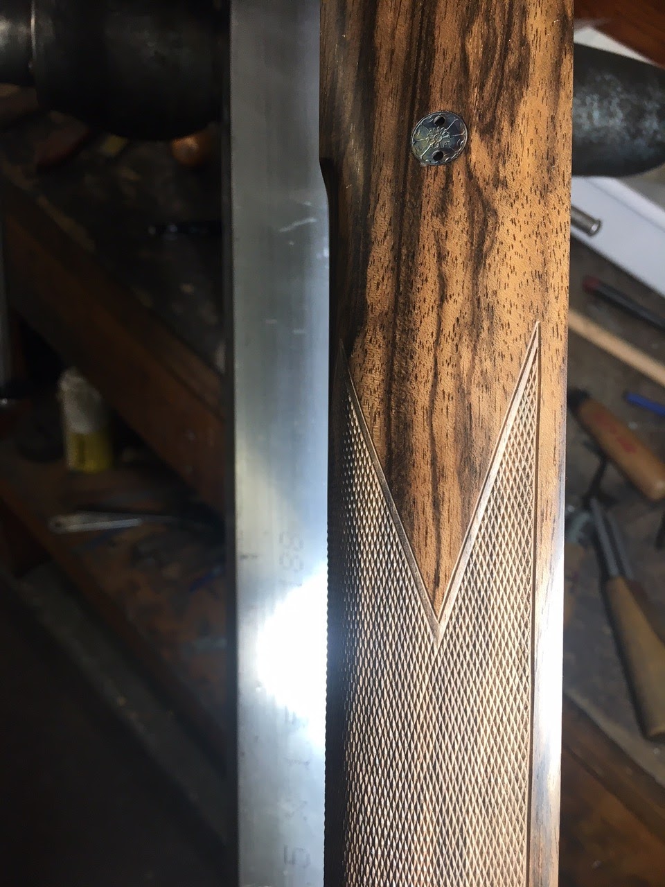
The stock was checkered 24 Lines per inch with an open point pattern. Nothing ornate but very functional.
Checkering complete I now moved onto the final metal-work. Lb wanted the standard minimal engraving on the metal-work but did have an interesting badging idea. I stepped to the side and began the final polishing. Illustrator Dan Burr and the team at CVM went to work to create the badging concept LB had in mind. All the this tilting lay out design work was done by CNC on a test block before the real receiver was bolted into the vise.
The team had a few mis-starts and corrections to make but the final results turned out very nice indeed.
Final assembly complete and I took the rest of the day off and went fishing.


%20B&W.jpeg)


.jpeg)