Below are a few pics from last summer, fall and this spring where Echols & Co. rifles


Below are a few pics from last summer, fall and this spring where Echols & Co. rifles
Having sent more than my share of bullets down range over the last 4 decades my right shoulder has developed Brachial Plexitis. This limits me to how many rounds I shoot each time I go to the range and what recoil levels I should stay away from. This 450 Rigby falls into the DO NOT SHOOT category. Loading the test fire rounds reminded me of how much I had begun to loathe this part of the job. Time to call Roger Inman again and he quickly confirmed that the rifle did feed and function at speed and that the sights were close enough to continue the construction.
LB pitched up and handled the rifle, he was all smiles so we headed to the range. Having been educated from the school of hard knocks I elected to pass on the typical bench top and we started shooting from my standing bench. The target frame was 70 yards from the bench top when LB touched off the 1st round. I happened to capture the recoil event on my iPhone and the image is quite revealing. It was evident that LB's Left hand has completely left the grip. I include this pic in no way to embarrass LB, but to illustrate that when you get into the heavy caliber recoil zone that a lot goes on during that millisecond of time as the bullet heads down range. This event is hardly a "one off "case I have seen it happen numerous times in the past when a client shoots a rifle heavy caliber rifle that is new to them.
I showed LB the pic and he was shocked. Note: that that his hand off the pistol (he knew that) grip, but that I had captured it on my phone. Now aware of the situation and a little miffed I wouldn't delete the pic, He applied more tension to his grip hand didn't have a repeat. Apply checkering to the grip and fore-end and the loose rifle event simply goes away. As they say a picture can be worth a thousand words.

After a 3 or 4 rounds Lb began to settle into the rifles recoil idiosyncrasies so we began to work on sight regulation. The Iron Sights I've preferred to install for decades has been a receiver sight I manufacture that is adjustable for windage at the rear sight and the elevation regulated by the height of the front sight. This sight system is simple, easier to use with aging eyes and not easily fiddled with by curious hands once the final adjustments have been made.
LB wanted a barrel band front sight base so I chose a Recknagel Universal with the built in elevation adjustment feature. Being color blind as well then LB could pick and choose from a variety of bead colors as to which one he could see best.


.jpeg)
Part 4 is going to be lacking some pictorial support. My I Phone which contained all but a few of the inletting, shaping and sanding pics went to the bottom of the Tallulah river in Northern GA.
Stock Fit, where to start? How many times have you heard the phrase " I want my DGR's to fit and point like a fine bird gun". Not me thank you.
Let me be 1st to admit that you can use almost any commercially made rifle to hunt dangerous game, admittedly some handle better than others for this application. The Pre-64 Winchester Model 70 375's and 458's are great examples if you can use the average LOP of 13-1/2" to 13-5/8 " and are Right Handed. The straight comb height on the older versions allowed most hunters to acquire the factory iron sights very well. The later Monte Carlo Version worked out equally well with a low mounted scope from that era such as the 2.5X to 3X and the later 1.5x20 Leupold.
Like a good suit you can tailor fit an iron sight rifle stock with the proper comb height to allow you to acquire the line of sight without having to cram your head into the side of the butt and down onto the comb. Usually the iron sights I fabricate are approximately 1.000 above the centerline of the bore.
Put a scope on that same rifle and most people will still be able to shoot it effectively even while having to very slightly raise their face off the comb to get the full field of view in the scope which is now mounted so the optical line of sight is 1.5" above the centerline of the bore.
Conversely if you build a stock with just enough clearance at the nose of comb for the cocking piece to clear and continue that same comb height rearward to the heel and then try to use most iron sights mounted low on the barrel and your likely to have issues even seeing the sights using that comb height. Again your milage might vary as everybody is different.
Again, this stock was to be tailor fit to a left-handed client with a bent trigger finger.
LB walked into the shop early on a Fall morning and we went to work. With the pattern stock and complete barreled action bolted together we began the final refining the fit of the butt stock with the LB lifting and pointing the muzzle at nearby objects, at the ground, into the sky and more importantly directly at my right eye many, many times. LB being an experienced rifle and shotgun hand was no novice to this and other past fitting sessions.
There were no misconceptions about trying to give this rifle the dynamics of 28 gauge quail gun, a Clays gun or for that matter a typical hunting rifle. The goal was to allow the rifle be brought to bare quickly, giving the rifle a comfortable balance and point ability allowing LB to direct a single bullet accurately on demand from 5 to 100 yards and operated the bolt at speed for rapid follow up shots if required.
A properly designed an iron sight rifle stock to some degree becomes the rear sight similar to a shotgun stock. Hence the attention to LB's required length of pull, cast on at the heel and toe, pitch angle, and the comb height at the face position on the butt when the rifle was mounted quickly or casually. My end goal was the have the front ramp pointing vertically at 12 Clock and have LB's left eye looking as straight down the barrel when viewed from the muzzle end.
The objective was to give the rifle balance the dynamics for the execution of an accurate shot, controlling the recoil as best as possible, allowing recoil recovery for a follow up shot or three if the situation required it.
Having built quite a number of heavy rifles over my career I already had a good idea of where these dimensions were headed but as stated before, I am not left handed, You can always guess or you can fit.


D'Arcy picks up the 450 story again in part 3
"As mentioned before this FZH receiver was ordered in the annealed state to allow the required machine work to be completed without the use of carbide tooling. It was time to ship the receiver and bolt off to be carburized.
If you wanted to start a lively argument on the subject of re-heated treating 98's toss out this question in a scrum of rifle builders anywhere in the world, trades shows and conventions are the perfect venue. Liberal alcohol should be applied say an hour before you start this discussion. Let's just say opinions will very.
This FZH is made from a modern carbon steel with its DNA and heat treating requirements well established and easy to acquire the proper surface hardness and penetration depth when done by professionals.
In due time both parts returned and the work began to re-polish the bolt body and receiver. Yes you can chemically strip off some of the scale and then bead blast the surfaces but the final work is a loathsome job requiring tedious hours of hand work, especially the 2nd time around. But you now have a complete surface envelope of hardened steel on your modified receiver and bolt body.

Once re-polished the receiver face, inner collar, bolt face, lug seats and the rear face of the recoil lugs are trued once again. These operations were all done prior to heat treatment but during the carburizing process some minor warpage will occur, it is inevitable. If you're lucky very little material will have to be removed .001 or less would be typical on each surface.
Now the the barrel is properly head spaced by calculating the math and setting back our pre-chambered barrel to accomplish this task, compared to polishing this is easy work. Gauges confirm we have everything in order and dummy rounds are again fed through the barreled action to ensure all is well in the Galaxy6. With the exception of the sight work the metal-work is functional and ready for the pattern stock.
If you have followed this blog at all you know I prefer to use a pantograph and pattern stock, period. However I did not have a drop box magnum left handed pattern in my inventory. I had couple left hand patterns for Model 70's so I cut the butt section off a right hand 98 long magnum pattern as well a butt stock from a left hand stock and went to work. Sort of like grafting apple trees.


.jpeg)
When I felt the pattern was pretty close to what we'd need, I installed a secondary recoil lug that was both screwed and soldered on the bottom side of the barrel shank. This barrel would be free-floated once completed so placing the second lug 5" or so forward the receiver would be useless, to say the least. I then installed a Universal Recknagel banded front sight ramp. Normally I would make the front sight ramp which would allow me all kinds of height adjustment correction during the sight regulation process something that was now quite limited with the banded design. I was reminded of the quote from Chief Dan George in the movie The Outlaw Josey Wales "We endeavored to persevere", and so I did.
It was at this stage, I called a good friend of mine in town who is also left-handed and serves as my test engineer when left handle issue have to be addressed. I handed Roger the 450 and asked him to step outside and mount the rifle quite a few times and give me his impression. As I am a devout right handed shooter that is not all the fond of palm swells I just couldn't get the right feel for what I'd put together. Roger is a keen rifleman and has shot a few buffalo so any input would be appreciated at this point. I got the thumbs up and I went back to work.
The barreled action was now glass bedded into the pattern stock and the selected piece of California English Walnut was put into the Hoenig Pantograph and cut .250 oversized externally and internally from the pattern then removed from the machine and hung on a peg to breathe. In this roughed state any internal demons bound up in that blank were hopefully set free.
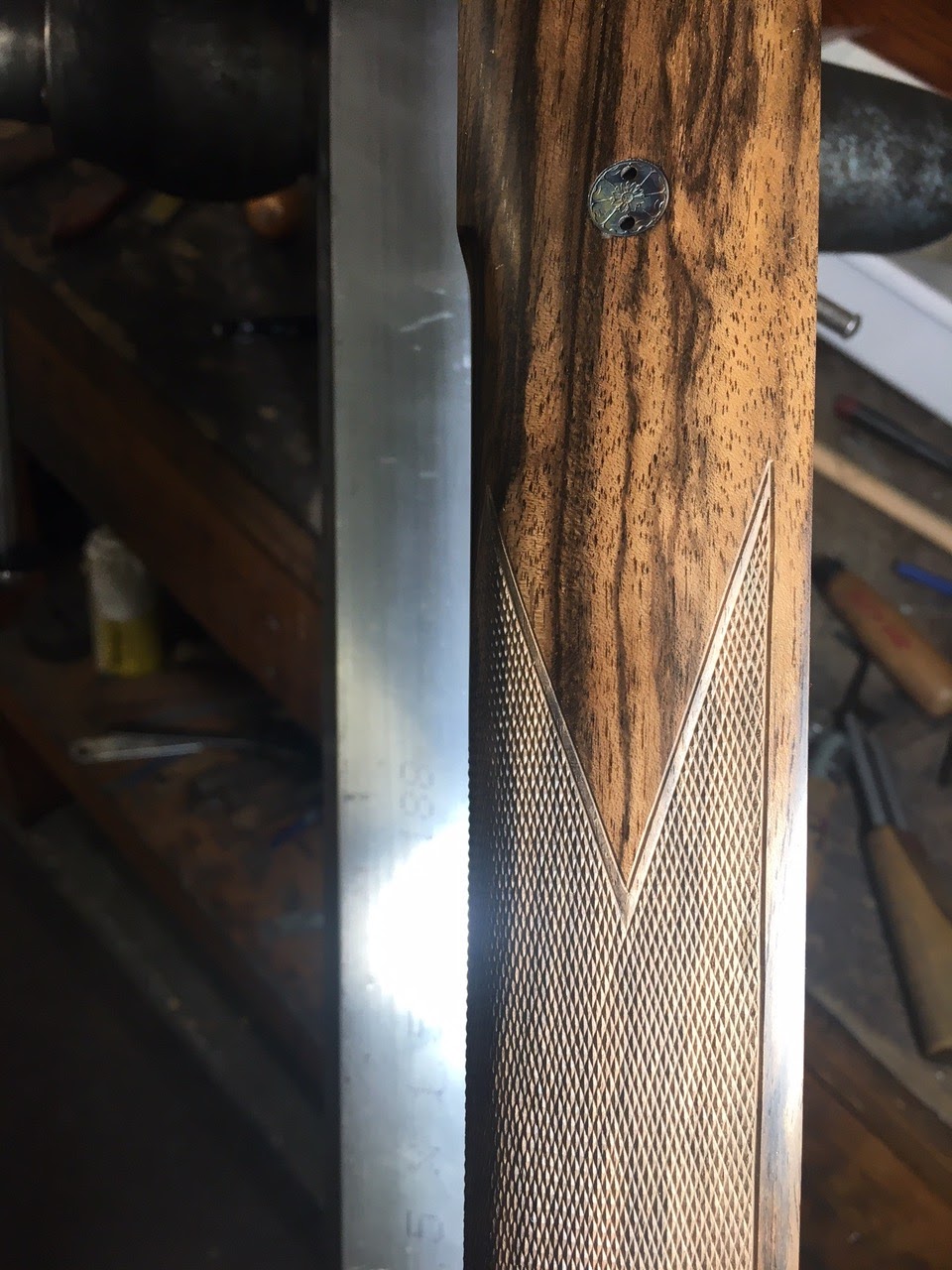
While installing the barrel band front ramp I also installed a Recknagel barrel band swivel base and cut a dovetail slot into the rear square bridge to accept my rear receiver sight base. Doing some preliminary math gave me the approximate heights required to first shots close to the desired point of impact.

