Sunday, November 3, 2024

450 Rigby Part 5

Having sent more than my share of bullets down range over the last 4 decades my right shoulder has developed Brachial Plexitis. This limits me to how many rounds I shoot each time I go to the range and what recoil levels I should stay away from. This 450 Rigby falls into the DO NOT SHOOT category. Loading the test fire rounds reminded me of how much I had begun to loathe this part of the job. Time to call Roger Inman again and he quickly confirmed that the rifle did feed and function at speed and that the sights were close enough to continue the construction. 

LB pitched up and handled the rifle, he was all smiles so we headed to the range. Having been educated from the school of hard knocks I elected to pass on the typical bench top and we started shooting from my standing bench. The target frame was 70 yards from the bench top when LB touched off the 1st round. I happened to capture the recoil event on my iPhone and the image is quite revealing. It was evident that LB's Left hand has completely left the grip. I include this pic in no way to embarrass LB, but to illustrate that when you get into the heavy caliber recoil zone that a lot goes on during that millisecond of time as the bullet heads down range. This event is hardly a "one off "case I have seen it happen numerous times in the past when a client shoots a rifle heavy caliber rifle that is new to them. 

I showed LB the pic and he was shocked. Note: that that his hand off the pistol (he knew that) grip, but that I had captured it on my phone. Now aware of the situation and a little miffed I wouldn't delete the pic, He applied more tension to his grip hand didn't have a repeat. Apply checkering to the grip and fore-end and the loose rifle event simply goes away. As they say a picture can be worth a thousand words.

After a 3 or 4 rounds Lb began to settle into the rifles recoil idiosyncrasies so we began to work on sight regulation. The Iron Sights I've preferred to install for decades has been a receiver sight I manufacture that is adjustable for windage at the rear sight and the elevation regulated by the height of the front sight.  This sight system is simple, easier to use with aging eyes and not easily fiddled with by curious hands once the final adjustments have been made. 

LB wanted a barrel band front sight base so I chose a Recknagel Universal with the built in elevation adjustment feature. Being color blind as well then LB could pick and choose from a variety of bead colors as to which one he could see best. 


Over the next day the range sessions fell into sync and LB was shooting the rifle very well off hand. We started off shooting Barnes 500gr TSX's and Barnes Solids. Later Lb settled on the Barnes 450gr TSX and Solid for Buffalo hunting. Sight regulation complete it was a now time to checker, engrave and blue the rifle. 


The stock was checkered 24 Lines per inch with an open point pattern. Nothing ornate but very functional. 


Checkering complete I now moved onto the final metal-work. Lb wanted the standard minimal engraving on the metal-work but did have an interesting badging idea. I stepped to the side and began the final polishing. Illustrator Dan Burr and the team at CVM went to work to create the badging concept LB had in mind. All the this tilting lay out design work was done by CNC on a test block before the real receiver was bolted into the vise.


The team had a few mis-starts and corrections to make but the final results turned out very nice indeed. 


Final assembly complete and I took the rest of the day off and went fishing. 


Wednesday, August 28, 2024

450 Rigby Part 4


Part 4 is going to be lacking some pictorial support. My I Phone which contained all but a few of the inletting, shaping and sanding pics went to the bottom of the Tallulah river in Northern GA. 

Stock Fit, where to start?  How many times have you heard the phrase " I want my DGR's to fit and point like a fine bird gun". Not me thank you.

Let me be 1st to admit that you can use almost any commercially made rifle to hunt dangerous game, admittedly some handle better than others for this application. The Pre-64 Winchester Model 70 375's and 458's are great examples if you can use the average LOP of 13-1/2" to 13-5/8 " and are Right Handed. The straight comb height on the older versions allowed most hunters to acquire the factory iron sights very well. The later Monte Carlo Version worked out equally well with a low mounted scope from that era such as the 2.5X to 3X and the later 1.5x20 Leupold.

Like a good suit you can tailor fit an iron sight rifle stock with the proper comb height to allow you to acquire the line of sight without having to cram your head into the side of the butt and down onto the comb. Usually the iron sights I fabricate are approximately 1.000 above the centerline of the bore. 

Put a scope on that same rifle and most people will still be able to shoot it effectively even while having to very slightly raise their face off the comb to get the full field of view in the scope which is now mounted so the optical line of sight is 1.5" above the centerline of the bore.

Conversely if you build a stock with just enough clearance at the nose of comb for the cocking piece to clear and continue that same comb height rearward to the heel and then try to use most iron sights mounted low on the barrel and your likely to have issues even seeing the sights using that comb height. Again your milage might vary as everybody is different.

Again, this stock was to be tailor fit to a left-handed client with a bent trigger finger.

LB walked into the shop early on a Fall morning and we went to work. With the pattern stock and complete barreled action bolted together we began the final refining the fit of the butt stock with the LB lifting and pointing the muzzle at nearby objects, at the ground, into the sky and more importantly directly at my right eye many, many times. LB being an experienced rifle and shotgun hand was no novice to this and other past fitting sessions.

There were no misconceptions about trying to give this rifle the dynamics of 28 gauge quail gun, a Clays gun or for that matter a typical hunting rifle. The goal was to allow the rifle be brought to bare quickly, giving the rifle a comfortable balance and point ability allowing LB to direct a single bullet accurately on demand from 5 to 100 yards and operated the bolt at speed for rapid follow up shots if required. 

A properly designed an iron sight rifle stock to some degree becomes the rear sight similar to a shotgun stock. Hence the attention to LB's required length of pull, cast on at the heel and toe, pitch angle, and the comb height at the face position on the butt when the rifle was mounted quickly or casually. My end goal was the have the front ramp pointing vertically at 12 Clock and have LB's left eye looking as straight down the barrel when viewed from the muzzle end. 

The objective was to give the rifle balance the dynamics for the execution of an accurate shot, controlling the recoil as best as possible, allowing recoil recovery for a follow up shot or three if the situation required  it.

Having built quite a number of heavy rifles over my career I already had a good idea of where these dimensions were headed but as stated before, I am not left handed, You can always guess or you can fit. 

LB happy with the final results and headed off on a deer hunt. 

Then the French walnut stock was final inlet and final shaped per the specs we'd come up with. Despite some moaning in the back-ground in regard to using a pattern stock and a pantograph, the metal still must properly be fit by hand. 


At this point you'll have to use your imagination as the pic history remember is "swimming with the fishes".

With the final shaping complete the sanding process began. Then the cross bolts, recoil pad and rear swivel base were installed followed by sealer and the 1st coats of finish. The Wells trigger was now attached to the underside of the receiver again. 

The rifle was now ready to actually shoot, except for one small set back.

Up to this point the rifle had never been dry fired, there was no need. The safety wing and striker cam angle wasn't established or timed and didn't really need to be to test fire the rifle. I assembled the bolt sleeve, main spring and cocking piece group together, screwed into the back of the bolt body and cocked the 450 for the 1st time. I then squeezed the trigger to get an idea of what the trigger weight of pull might be like right out of the box. After I doing this procedure about 4 times I noticed that opening the bolt became considerably more difficult every time I dry fired the rifle, what the .........................

I unscrewed the bolt sleeve and pin assembly and removed it from the bolt body and immediately noticed the nose of the firing was bent. Not again !!!!


I was once again the owner of a bolt body that had a firing pin hole drilled off center into the bolt face. 


With a slip fit gauge pin inserted into the firing pin hole the issue is easy clearly evident 

Believe it or not this is the 2nd time I have had a similar bolt in my shop. The 1st being a Hartmann and Weiss magnum Mauser bolt suffering from the very same anomaly, lucky me. Rather than return the entire bolt to Germany as requested by H&W I sought out a master of what I knew was now required. 

I made a call to Greg Tannel owner and operator of Gre-Tan Rifles LLC and explained my dilemma. I described the issue to Greg he chuckled and  replied " no problem, send it over ". I straightened the firing pin tip in the lathe with a brass drift and an indicator then placed both the pin and the bolt body in a box and sent it to Greg and had him bush the bolt face, one of his many talents. In short order the surgically repaired bolt returned and I was finally ready for some range time. 


Saturday, July 27, 2024

450 Rigby Part 3

D'Arcy picks up the 450 story again in part 3 

"As mentioned before this FZH receiver was ordered in the annealed state to allow the required machine work to be completed without the use of carbide tooling. It was time to ship the receiver and bolt off to be carburized. 

If you wanted to start a lively argument on the subject of re-heated treating 98's toss out this question in a scrum of rifle builders anywhere in the world, trades shows and conventions are the perfect venue. Liberal alcohol should be applied say an hour before you start this discussion. Let's just say opinions will very. 

This FZH is made from a modern carbon steel with its DNA and heat treating requirements well established and easy to acquire the proper surface hardness and penetration depth when done by professionals.

In due time both parts returned and the work began to re-polish the bolt body and receiver. Yes you can chemically strip off some of the scale and then bead blast the surfaces but the final work is a loathsome job requiring tedious hours of hand work, especially the 2nd time around. But you now have a complete surface envelope of hardened steel on your modified receiver and bolt body.

Once re-polished the receiver face, inner collar, bolt face, lug seats and the rear face of the recoil lugs are trued once again. These operations were all done prior to heat treatment but during the carburizing process  some minor warpage will occur, it is inevitable. If you're lucky very little material will have to be removed  .001 or less would be typical on each surface.

Now the the barrel is properly head spaced by calculating the math and setting back our pre-chambered barrel to accomplish this task, compared to polishing this is easy work. Gauges confirm we have everything in order and dummy rounds are again fed through the barreled action to ensure all is well in the Galaxy6. With the exception of the sight work the metal-work is functional and ready for the pattern stock. 

If you have followed this blog at all you know I prefer to use a pantograph and pattern stock, period. However I did not have a drop box magnum left handed pattern in my inventory. I had couple left hand patterns for Model 70's so I cut the butt section off a right hand 98 long magnum pattern as well a butt stock from a left hand stock and went to work. Sort of like grafting apple trees. 


Having built quite a few iron sight rifles using my receiver sights I have had a fair idea of what my typical LOP, drop and cast measurements were going to be. If you look at these pattern stocks you can already see where the cut pattern has been altered in the past for a previous project, note the saw cut just ahead of the comb nose and the wooden dowel exposed mid way down the grip. Visible below the dowel you can see Bondo and Marine Tex filling in the voids that held the whole thing together. The same application is applied here, cut, move, and splice. Right hand to left, add a bolt stop shelf to the opposite side, more drop, less drop, cast off or on, whatever is required so the client can mount the rifle and be looking down the line of sight comfortably. This grip would feature a Wundhammer swell and a few other cosmetic effects to the comb nose and cheek piece that are out of the ordinary for me, but LB had left index finger damaged in his youth so we needed to deal with how to allow him to best reach to the trigger lever and quickly as this rifle would not be used on ground squirrels. 


When I felt the pattern was pretty close to what we'd need, I installed a secondary recoil lug that was both screwed and soldered on the bottom side of the barrel shank. This barrel would be free-floated once completed so placing the second lug  5" or so forward the receiver would be useless, to say the least. I then installed a Universal Recknagel banded front sight ramp. Normally I would make the front sight ramp which would allow me all kinds of height adjustment correction during the sight regulation process something that was now quite limited with the banded design. I was reminded of the quote from Chief Dan George in the movie The Outlaw Josey Wales "We endeavored to persevere", and so I did. 

It was at this stage, I called a good friend of mine in town who is also left-handed and serves as my test engineer when left handle issue have to be addressed. I handed Roger the 450 and asked him to step outside and mount the rifle quite a few times and give me his impression. As I am a devout right handed shooter that is not all the fond of palm swells I just couldn't get the right feel for what I'd put together. Roger is a keen rifleman and has shot a few buffalo so any input would be appreciated at this point. I got the thumbs up and I went back to work. 

The barreled action was now glass bedded into the pattern stock and the selected piece of California English Walnut was put into the Hoenig Pantograph and cut .250 oversized externally and internally from the pattern then removed from the machine and hung on a peg to breathe. In this roughed state any internal demons bound up in that blank were hopefully set free. 

While installing the barrel band front ramp I also installed a Recknagel barrel band swivel base and cut a dovetail slot into the rear square bridge to accept my rear receiver sight base. Doing some preliminary math gave me the approximate heights required to first shots close to the desired point of impact. 


LB would soon be in the area on his way to hunt deer in Wyoming and a shop visit was planned for him to handle the assembled work to date and allow me to fine tune the pattern as I stood by with a collection of rasp and files and watched him mount the rifle. 

Thursday, January 18, 2024

The 450 Rigby Part 2


I'll let D'Arcy pick this up again


The action work began with addressing the bolt. After indicating the part in the lathe, I began by opening the bolt face from the standard belted magnum diameter to the larger diameter of the 450 Rigby rim diameter plus .005”. With this operation complete, the bolt was removed from the lathe and transferred to the mill. Inverted vertically in a dedicated fixture, I carefully re-contoured the surfaces to allow the larger cartridge case rims to roll in under the extractor hook and into the bolt face as the bolt pushed the cartridges forward and out of the feed well. 


The FZH-supplied extractor was then modified with a few select needle files and reshaped to work in harmony with the bolt face and the provided Norma brass. The function of this operation alone is what gave the claw extractor system the street cred that it has had since day one. Done improperly, it either retards feeding, or worse, renders the entire system into a push-feed receiver. I allowed .005” to .007” of extractor tension applied between the hook and the extractor groove of the case, once I had everything correctly timed. The carefully contoured face of this extractor and the added clearance machined in the extractor slot side of the receiver allowed the bolt to be closed over a round dropped directly into the chamber and will give the shooter one additional round in total capacity.   


The OEM-supplied FZH bolt handle was removed and a new bolt knob that had been previously checkered and engraved was installed. Traditional big-bore aesthetics aside, I prefer to sweep the bolt handle to rear by about 15 degrees.  The client agreed.  “I think it looks better,” L.B. told me. “But, more importantly, it shortens the length from grip to bolt face which makes bolt operation easier, and much easier under stress. 15 [degrees] is about right for aesthetics and function. Moving the bolt head any more to the rear risks bumping the strong hand trigger finger knuckle under recoil.”  


The notch for the modified bolt handle root or base was then machined into the correct position, angle and depth to allow the bolt body to align the recoil lugs into the required vertical 6 and 12 o’clock positions when engaged with the recoil seats within the front ring while in-battery.


Now, it was time to modify the receiver. As requested, the topside of the completely annealed receiver had been machined for a 375 H&H-length cartridge. This allowed me maximum flexibility since it’s far easier to remove steel than to add it back on—I never was much of a welder. 
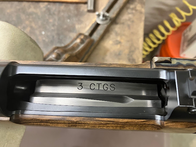

Snaking rounds into a magazine as one is back peddling and trying to reload when a situation goes south is not as exciting as it sounds. It was necessary to create a system that was easy to load under stress, which meant opening the ejection port to the correct dimensions. The 450 Rigby cartridge is typically loaded to a 3.750” overall length, so the ejection port and rear bridge on this receiver were modified to allow a loaded round of this length to be loaded easily through the top of the port or the extended left side of the of the receiver. Almost 1/8” of material was removed from the rear bridge alone. I also wanted to remove the front square bridge to allow the rifle to be carried with one hand and not suffer the pain of those four corners getting in the way.


     From the mill to the surface grinder 


     The receiver was then returned to the milling fixture with the bottom side facing up. If there was ever a time to measure five times and cut once, that moment had arrived.


    A longitudinal slot was machined through the feed well and into the bolt raceway that would soon be wide enough for the 450 Rigby round.


 To allow me to set the magazine assembly on the receiver, I had to cut the slot for the rear standing tab at the back of the mag box first. This tab centers the magazine box opening directly under the receiver’s feed well so cutting this cavity required attention to detail.


        Tooling was then selected to plunge through the bottom side of the receiver and into the bolt raceway. At this point, the phone gets placed in the car and the shop door is locked. With a variety of standard and ball end mills, the correct depths and tapers of the feed well, angles and radii were then established.


    With the slot cut to the correct depth and width, the assembly was able to sit flush on the receiver. With both guard screws finger-tight you could visually see and lay out with a scribe the edges of the inside of the magazine box. These edges were used as a reference to compare with the crib note diagrams that I may or may not have scribbled on a napkin.

    The magazine box was installed over the feed well one last time to make sure all the required steel had been removed. Only then was the receiver removed from the fixture. 


 Now a mandrel was screwed into the receiver and, with the mandrel held in the bench vise, I begin to use mold making stones on all of the machined surfaces blending and removing the machine marks and smoothing the transitions. 


At this point, it was time to install the barrel by indicating it in with a gimbal set up ala Hambly-Clark, Jr. This precise method has become the only one that I will use in my shop to thread, fit and chamber a barrel. I would be using this chambered barrel to set up the feeding while the bolt and receiver were still in their annealed state. The chamber was cut with the Henriksen reamer and intentionally run .008” to .010” deeper than required for the feeding process to be begin. Later, the barrel would be set back to establish the proper headspace after the heat-treating process of the bolt and receiver had been completed. 


With the barrel now installed hand-tight, I attached the bolt stop, the completely assembled magazine, the newly fabricated follower and a generic w-shaped magazine spring. I begin to run dummy 450 Rigby cartridges from the magazine into the chamber. The bullet ramp was addressed first using rotary carbide burs, then rotary stones followed by needle files and experience. Test feeding and fitting began with one cartridge at a time coming off the follower first, then two at a time, and continued until the entire loaded magazine would feed. During this exercise, I also determined the best magazine spring to use with this cartridge payload. Not all springs are the same-- not all of them collapse or shift forward and rearward the same and, using a large selection of springs, I tried and eventually found the best spring for this application. 


It is important to pay attention to how the cartridges leave the mag box, where the bullet nose first engages the bullet ramp as well as the path that the bullet takes as it travels up the ramp. If you begin this procedure with a spitzer or round nose and you believe you’ve got your mag box, feed well and rails just like you want them. It’s now time to make up a complement of flat-nose dummies and run these through your receiver group.This can be quite humbling on the first go round. I prefer to use the Barnes Flat Nose Solids as my dummy bullet standard.


If and only if, these flat-nose rounds behave and show no resistance when being run into the chamber at the same speed that you might use at the range, then it’s time to move onto the next phase. 


Next, the bolt body and receiver as well as the striker, safety wing and bolt shroud are hand polished to a 220-grit finish. These nicely polished parts were sent off to be surface hardened in a carburizing process. Only then, once all of the components are at their final hardness, do I dare run the bolt at speed to allow me to do the final feed work. This "at speed" test is ultimately separates the chickens from the pigs. In the words of one of my favorite bands "It's a long way to the top if you want to rock and roll"